

Description
Basic specifications
| Measurement modes | LCR (Measurement with single condition), Continuous testing (Continuous measurement under saved conditions) | |||||
|---|---|---|---|---|---|---|
| Measurement parameters | Z, Y, θ, X, G, B, Q, Rdc (DC resistance), Rs (ESR), Rp, Ls, Lp, Cs, Cp, D (tanδ), σ, ε | |||||
| Measurement range | 100 mΩ to 100 MΩ, 10 ranges (All parameters are determined according to Z) | |||||
| Display range | Z: 0.00 m to 9.99999 GΩ, Y: 0.000 n to 9.99999 GS, θ: ± (0.000° to 180.000°), Q: ± (0.00 to 9999.99), Rdc: ± (0.00 m to 9.99999 GΩ), D: ± (0.00000 to 9.99999), Δ%: ± (0.000 % to 999.999 %), or other |
|||||
| Basic accuracy | Z ±0.05% rdg. θ: ±0.03° (representative value, Measurable range: 1 mΩ to 200 MΩ) | |||||
| Measurement frequency | 4 Hz to 8 MHz (5 digits setting resolution, minimum resolution 10 mHz) | |||||
| Measurement signal level | [Normal mode: V mode/CV mode] 4 Hz to 1.0000 MHz: 10 mV to 5 Vrms (maximum 50 mArms) 1.0001 MHz to 8 MHz: 10 mV to 1 Vrms (maximum 10mArms) [Low impedance high accuracy mode: V mode/CV mode] 4 Hz to 1.0000 MHz: 10 mV to 1 Vrms (maximum 100 mArms) [Normal mode: CC mode] 4 Hz to 1.0000 MHz: 10 μA to 50 mArms (maximum 5 Vrms) 1.0001 MHz to 8 MHz: 10 μA to 10 mArms (maximum 1 Vrms) [Low impedance high accuracy mode: CC mode] 4 Hz to 1.0000 MHz: 10 μA to 100 mArms (maximum 1 Vrms) [DC resistance measurement] Measurement signal level: Fixed at 1 V |
|||||
| DC bias measurement | Generating range: DC voltage 0 V to 2.50 V (10 mV resolution) In low Z high accuracy mode: 0 V to 1 V (10 mV resolution) |
|||||
| Output impedance | Normal mode: 100 Ω, Low impedance high accuracy mode: 10 Ω | |||||
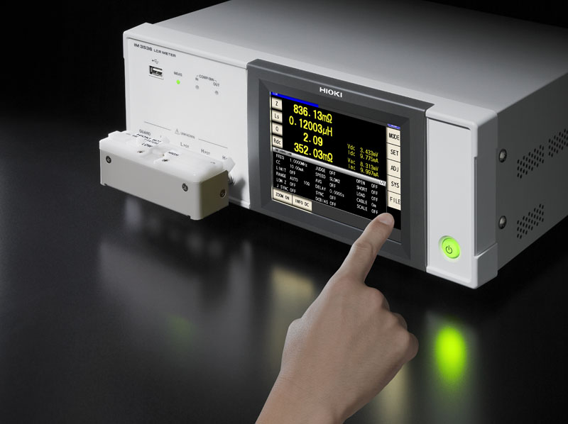
| Display | 5.7-inch color TFT with touch panel | |||||
| Functions | Comparator, BIN measurement (10 categories for 2 measurement parameters), Trigger function, Open/short compensation, Contact check, Panel loading/saving, Memory function | |||||
| Interfaces | EXT. I/O( HANDLER) ,USB, USB flash drive, LAN, GP-IB, RS-232C, BCD | |||||
| Power supply | 100 to 240 V AC, 50/60 Hz, 50 VA max. | |||||
| Dimensions and mass | 330 mm (12.99 in) W × 119 mm (4.69 in) H × 230 mm (9.06 in) D, 4.2 kg (148.1 oz) | |||||
| Included accessories | Power cord ×1, Instruction manual ×1, LCR application disc (Communications user manual) ×1 | |||||
Measuring the Capacitance of Electrolytic Capacitors with Hioki LCR Meters
The measurement conditions under which the capacitance of electrolytic capacitors is defined are set forth by an IEC standard. However, since the capacitance of electrolytic capacitors varies significantly with the measurement frequency, capacitance values are also checked at the frequencies that correspond to the circuit conditions under which the components will actually be used. The LCR Meter IM3536’s measurement frequency can be set over a broad range of values (DC and 4 Hz to 8 MHz), making the instrument ideal for evaluating components under the conditions of actual use.
Measuring the Capacitance of Ceramic Capacitors with Hioki LCR Meters
There are two types of laminated ceramic capacitor: the high-dielectric type, whose capacitance varies with the measurement voltage, and the temperature-corrected type, whose capacitance does not vary. The measurement conditions under which capacitance is defined are set forth by separate IEC standards for the two types of component. The LCR Meter IM3536’s measurement frequency and measurement voltage can be set over a broad range of values (DC and 4 Hz to 8 MHz, and 10 mV to 5 V, respectively), making the instrument ideal for measuring laminated ceramic capacitors under a variety of conditions.
Measuring the Inductance of Inductors or Coils with Hioki LCR Meters
The phenomenon of LC resonance based on the inductance of inductors (or coils) and the parasitic capacitance of coils is known as self-resonance, and the frequency at which self-resonance occurs is known as the self-resonant frequency. When evaluating a coil, measure L and Q at a frequency that is sufficiently lower than the self-resonant frequency. The LCR Meter IM3536’s measurement frequency can be set over a broad range of values (DC and 4 Hz to 8 MHz), making the instrument ideal for measuring and evaluating components while varying the frequency.
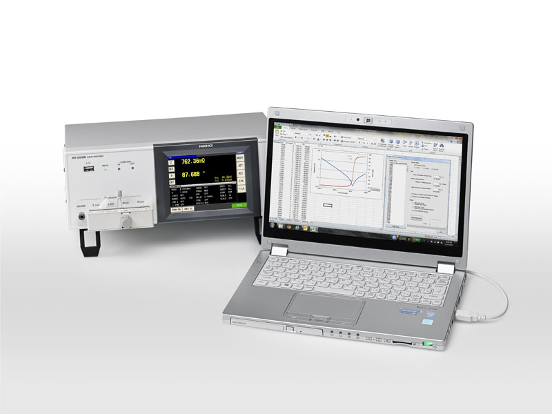
Measuring the Frequency Characteristics of Inductors on Hioki LCR Meters
The LCR Meter IM3536’s measurement frequency can be set over a broad range of values (DC and 4 Hz to 8 MHz), making it ideal for measuring and evaluating components while varying the frequency. You can install the included LCR sample application software (CD-R) on a computer and use it via the instrument’s interfaces (USB, GP-IB, or RS-232C) to vary the frequency at designated points and to save data obtained from automatic measurement as a Microsoft Excel or text file.


